RWC Alarm – Complete Alarm Kit for Emergency Situations including Power Supply – CE Marked

🟢 1 pc in stock - Delivery 1-2 days (more can be ordered)
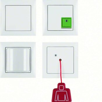
RWC Alarm is a complete emergency alarm system for accessible toilets and other spaces where help may be needed quickly.
With a pull cord, alarm button and sound/light signaling, this system ensures a quick response in emergency situations. Easy installation and high operational reliability make it an excellent choice for public environments.
Item number: RWC KIT
2521,00 kr
RWC Alarm is a reliable and user-friendly solution for increasing safety in restrooms and other accessible environments.
The RWC alarm is connected with a 2-wire cable or 4-wire cable. The power supply is connected via an electrical cable to 220V.
The system is designed to enable rapid assistance in emergency situations through a clear alarm indication.
Features and benefits of this RWC Alarm:
- Complete package – Includes emergency button, pull cord and alarm indicator.
- Clear alarm indication – Sound and light signaling for immediate attention.
- User friendly – Easy to activate, even for people with limited mobility.
- Easy to install – Suitable for public toilets, healthcare facilities and businesses.
- High operational reliability – Robust design with reliable functionality.
Areas of use for RWC Alarm – Emergency Alarm
- Public toilets
- Hospitals and care facilities
- Schools and workplaces
- Hotels and shopping malls
Technical specifications:
Power source: 12V–24V DC
Alarm type: Acoustic and visual indication
Mounting: Wall-mounted unit with pull cord
Material: Durable and easy to clean
Product Length/Depth: 280 mm
Product height: 48 mm
Product width: 211 mm
Product weight: 0.498 kg
Certifications: CE
RWC alarm installation
To ensure correct and safe installation of the toilet alarm, the following guidelines should be followed.
Electrical installation (Mains wiring)
- The power supply to the alarm control unit must be via a fixed installation with a three-core cable with an area of at least 1 mm².
- The connection should be made via a isolated, breakable and secured supply with a 3A fuse.
- The installation must be carried out in accordance with IEE Wiring Regulations (BS 7671) or applicable national electrical installation regulations.
Extra low voltage (ELV) wiring
- All low voltage wiring must be separated from the mains voltage.
- The system requires a at least 2-core cable (0.4 mm²).
- All wall-mounted units should be installed on a mounting frame with sufficient depth.
Wiring diagram – Connecting devices
The following connections should be made according to the wiring diagram:
-
Power supply (Power Supply, 12V)
- Connects to: Pull Cord device IN port.
-
Pull Cord Device
- IN port connected to the power supply.
- OUT port connected to the Cancel button (Cancel Unit).
-
Cancel button (Cancel Unit)
- IN port connects to the Pull Cord unit's OUT port.
- OUT port connected to the Over door indicator.
-
Over Door Indicator
- IN port connected to the Cancel button.
Overview of connections
| OUT port | IN port |
|---|---|
| PSU | Door indicator |
| Door indicator | Cancel button |
| Cancel button | Pull Cord Device |
Summary installation description
Quick Guide – RWC Alarm Installation
- Power supply: Connect the alarm to a fixed electrical installation with a 3A fuse and one 1 mm² cable.
- Low voltage wiring: Separate low voltage cables from the mains voltage and use at least 0.4 mm² cable.
- Coupling:
- Connect the power supply to The Pull Cord device.
- Connect The Pull Cord device to Cancel button.
- Connect Cancel button to The door indicator.
- Final check: Ensure that all devices are working by testing the alarm function.
| Brand/Make |
|---|
Related products
-
RWC Alarm
Emergency Alarm RWC Package - Safe and Effective Alarm and Indication System
Varumärke: TjedersEmergency alarm RWC Package from Tjeders - Complete Security Solution
Emergency alarm RWC Paket from Tjeders offers reliable safety monitoring with both acoustic and optical indication. The package includes call and reset devices and room light with buzzer. Alarms are easily activated and reset via softkeys, and the system can be routed for flexible integration. Ideal for security installations.
SKU: 5500546 -
RWC Alarm
RWC Package with Transformer Exxact - Complete Emergency Signal System
Varumärke: Schneider ElectricRWC package with transformer from the Schneider Electric Exxact series. Contains 1 emergency button, 1 emergency button with signal socket, 1 memory unit with reset/emergency button and 1 room light with buzzer. IP20 rated units in white color that can be completed with any Exxact frame.
SKU: 5506388