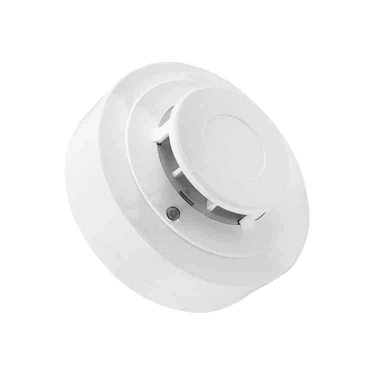
Heat detector 4 wire 9-35V HD504 – Complete, socket included
Heat detector 4 wire 9-35V with an effective solution for fire protection.
The HD504 heat detector offers a combination detection of temperature rise and fixed temperature, 57 degrees, with coaxial cable, which is perfect for both domestic and commercial applications.
Heat detector 4 wire 9-35V detector option consists of an externally mounted thermistor with a specially designed hood that protects the thermistor while allowing for maximum airflow.
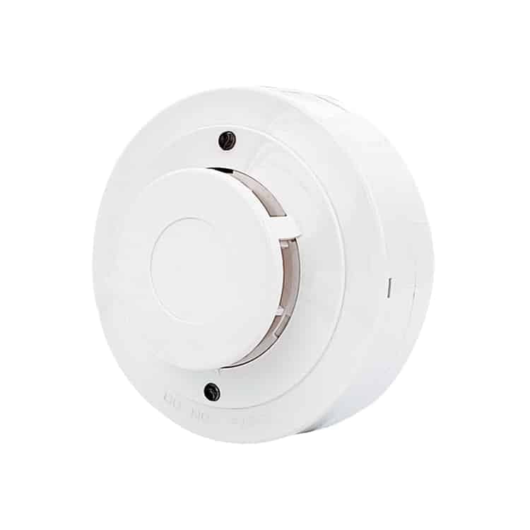
The thermistor measures the temperature of the incoming air and transmits a signal representing the temperature to the control IC.
If the temperature reaches or exceeds the threshold value, the detector is triggered. The status LED lights up red and the alarm's signal is activated.
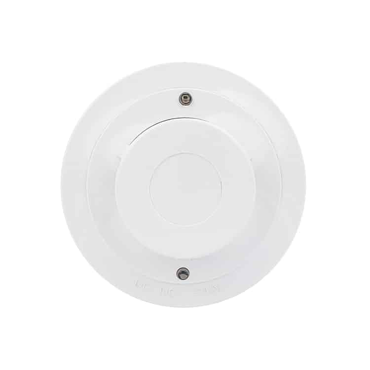
Product features for Heat detector 4 wire 9-35V
- Strong adaptability for different environments.
- SMT technology is used for high stability.
- Low standby current.
- Wide voltage range of 9-35VDC.
- Non-polarized current input.
- Flashing LED power indicator.
- Alarm relay C / NO Normally open in case of no alarm
- Remote LED indicator output (2-wire).
- Self-test function with magnetic switch (optional).
- Fixed temperature detection (default).
- Combined temperature rise and fixed temperature detection (optional).
Technical specifications Heat detector 4 wire 9-35V
Product category: 4-wire
Operating voltage: DC 9V35V
Standby power: ≤ 50uA, ≤ 50 uA (relay NO)
Alarm current: 2025 mA @12V, 4050 mA @24V, ≤ 40 mA (relay NO)
Alarm current: 2025 mA @12V, 4050 mA @24V, ≤ 40 mA (relay NO)
Temperature range: 0℃+50℃
Humidity: ≤ 95%RH (no condensation)
Temperature level: Fixed TEMP: 57℃(135℉)
Detection range: 50 m² at installation height of 6~12m
Alarm output: Remote LED, Relay Output Contact Rating: N/A, 0.5A@DC28V
Standard: EN54-5, UL521, GB4716-2005
Dimensions: 98.5mm diameter*43.5mm depth
Magnetic switch self-test:
Connect the detector to the circuit and place a magnet near the detector. If the detector is working normally, the red indicator light is on.
Test:
Simulate an environment to test the detector: place the detector in a chamber with a thermometer and use a heating device to raise the air temperature in the chamber.
When the temperature reaches the threshold value, the detector's LED lights continuously in red, and the alarm signal is activated.
Note:
- The detector cannot be installed in places exposed to direct sunlight or heat.
- It is recommended to install the detector near a smoke detector.
- Make sure the base is securely attached and all wire connections are correct.
- Test the detector every quarter.
Installation:
- Connect the wires to the mounting base.
- Choose a suitable location (normally mounted in the middle of the ceiling). Attach the mounting base, then insert the detector into the base and twist to secure.
Connection description:
Wire Diagram: 4-wire base connections:
Screw + on screw 2 and – minus on screw 5.
The relay is located on screw 3 for common and 6 for NO
Wire Diagram: 2-wire base connections:
- Power input jack 5. Power input input
- Power input input 6. Remote LED output
 Testgas TG-SABRE (SmokeSabre) – Handhållen röktestare för Rökdetektorer- Brandvarnare- och Brandlarm, 150 ml
  Battery CR2032 5-pack Button cell battery Lithium
 No advertising or free magazines please!
  CR123A Battery 3V - 1500 mAh Lithium